Products


 0
0


This article summarizes and organizes common issues engineers encounter during the selection and testing of power management ICs, offering quick answers to address these concerns. We encourage experts to add their insights and discuss further in the comments section.
Table of Contents:
The static current IQ listed in the datasheet refers to the current measured under test conditions with the chip in a non-switching state, where the internal MOSFETs are not active, and only the chip's logic circuits are in standby mode. On the board, when the chip is operating, the MOSFETs switch, leading to switching losses, driving losses, and additional losses from peripheral components like inductors, EN pin voltage dividers, and FB feedback resistors.
Therefore, even with no load on the board, the static current will be higher than the value specified in the datasheet.
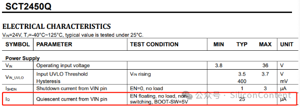
For example, with the SCT2450Q chip, the datasheet specifies an IQ of 25μA, but the measured idle input current on the demo board is around 80μA.
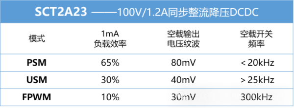
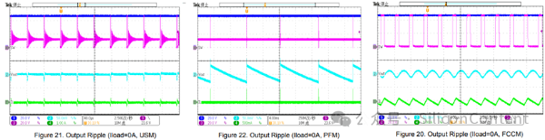
2. PSM (PFM), USM, FPWM (FCCM) Differences, Advantages, and Disadvantages: Why do some DCDC circuits exhibit inductor squealing noise?
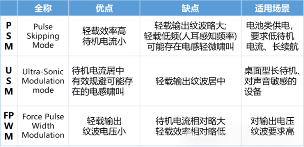
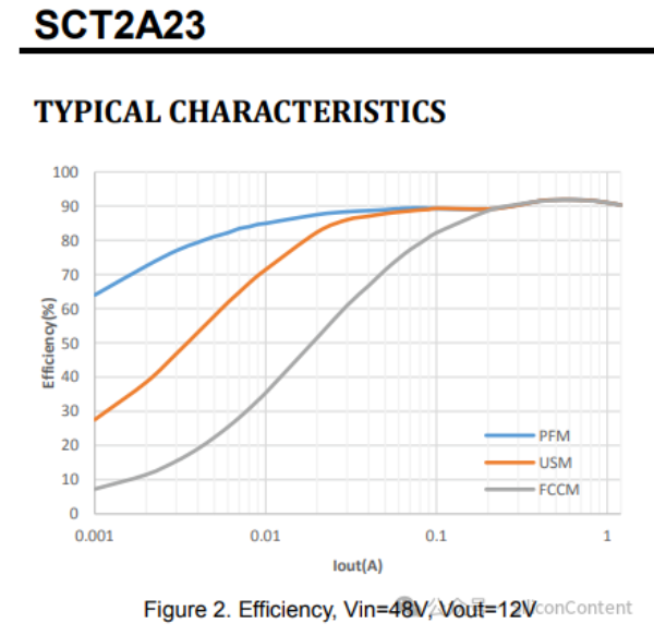
The SCT2A23 (100V/1.2A synchronous rectifier) chip offers three different operating modes:
UVLO (Under Voltage Lock-Out) refers to the input voltage threshold below which the chip will stop working. The rising threshold (UVLO Rising) is the input voltage at which the chip starts operating, while the hysteresis is the voltage difference between the rising and falling thresholds.
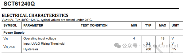
For example, the SCT61240Q has a rising voltage of 3.8V and a hysteresis of 0.2V, so the chip will start operating at 3.8V (Von) and shut down at 3.6V (Voff).
4. EN Enable Design Logic: How to Avoid Power-Up and Power-Down Oscillation Issues?
The EN (Enable) pin is used to control the chip's power-up and power-down behavior. By setting appropriate threshold voltages for the EN pin, we can ensure that the chip does not turn on or off at undesired moments, avoiding oscillations or instability due to incorrect voltage conditions during power-up or power-down.
EN Design Logic:
Vout > UVLO, the voltage at the EN pin (Voff) should be greater than Vout.
Vout < UVLO, the voltage at the EN pin (Voff) should be greater than UVLO.
Vhys > Vin_UVLO_Hysteresis of the chip.
For example, in the case of SCT2A00 (100V/0.6A DC-DC converter), the calculation formula for setting Von (start-up voltage) and Voff (shutdown voltage) through the EN pin is as follows: 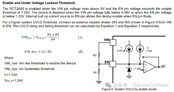
According to the calculation formula: The larger the pull-up resistor on the EN pin, the larger the hysteresis, which makes it less likely for the chip to repeatedly restart due to voltage feedback from the input voltage. The recommended value for the resistor from EN to ground should be smaller than Vin_fall/(I1+I2).
5. Soft-start: Solving issues like overshoot during power-up and failure to start under electronic load or heavy load
What is soft-start?
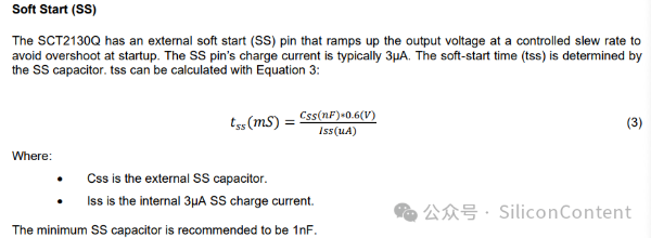
SS (Soft-start) is a feature designed for switching power supply circuits, providing a startup time during which the output voltage gradually rises to the target voltage value.
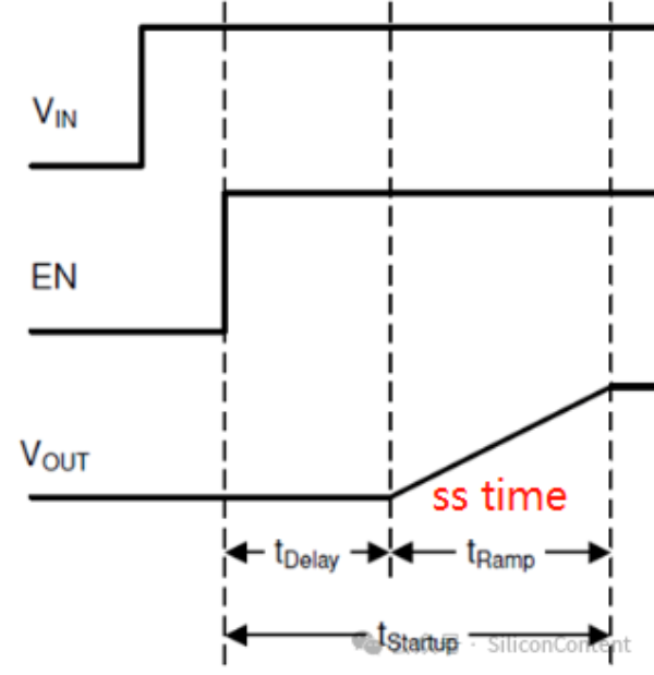
Soft-start time (SS time) refers to the duration it takes for the output voltage to rise from the start of the power-up process to the end of the startup.
Effects of Soft-start
Reducing surge current: Soft-start effectively suppresses inrush current, preventing the current during the initial charging of the output capacitor from reaching the switching power supply's limit, which would otherwise trigger protection.
When powering up with an electronic load and large output capacitors, the poor linearity of the system causes a significant surge current at power-up. As the voltage builds, it charges the large output capacitor. This combined effect can create a large load current during the voltage buildup, potentially triggering overcurrent protection and preventing the system from powering up.
Solving repeated restart issues: By reducing current stress on both the switching circuit and downstream load, soft-start minimizes the transient load current response at the input. This reduces the likelihood of input voltage dips that would lead to repeated restarts of the chip.
Solving overshoot and jitter: The soft-start function ensures the output voltage rises smoothly, avoiding jitter or overshoot due to fast power-up rates. This is especially important for digital devices, particularly FPGAs, which have strict power-up sequencing requirements. Soft-start helps prevent latch-up issues in downstream digital components or FPGA devices.
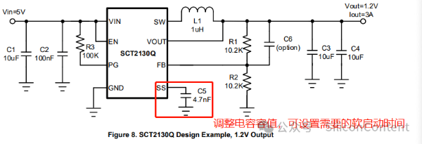
Selecting soft-start capacitor and time:
Choosing the appropriate capacitor and time for soft-start is crucial. A larger capacitor results in a longer discharge time, which may cause issues if the system undergoes rapid power cycling, as the soft-start capacitor might not discharge fully. This could lead to overshoot or other problems when the system powers up again.
The appropriate value should be selected based on the application; a larger capacitor and longer soft-start time are not always better. A larger capacitor will result in a longer discharge time. If there are frequent power cycling scenarios, the soft-start capacitor may not discharge fully before the system powers up again. This could prevent the soft-start process from being triggered properly, potentially causing issues such as overshoot in the output voltage when the system is powered on again.
6. Understanding Thermal Resistance and Calculating Chip Junction Temperature
Thermal resistance is an important parameter for estimating the chip's junction temperature (TJ). The table below shows typical thermal characteristics for the SCT2464Q (40V/6A BUCK, QFNFC4×3.5-14L Package). Common thermal resistance parameters include:
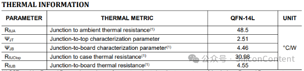
By understanding and calculating these thermal parameters, engineers can assess whether the selected MOSFET or power management chip will stay within safe thermal limits during operation.