Products


 0
0


For an excellent hardware engineer or device engineer, the quickest way to understand a chip is by reading its datasheet. A datasheet provides a detailed overview of the chip's specifications and parameters, helping engineers determine whether the chip meets the selection requirements and fits their application needs.
Datasheets can span dozens of pages, so to efficiently locate key information and parameters, one must be very familiar with the manual. In the following, we will analyze the datasheet of the SCT2464Q as an example. By exploring its sections, we aim to help engineers quickly grasp the contents of a datasheet after receiving the materials.
The structure of SCT products' datasheets is generally consistent. Datasheets for different product categories provide detailed explanations tailored to the specific characteristics of the products, typically divided into the following seven major sections (recommended to save the image):

After understanding the basic structure of a datasheet, does the complex information suddenly become clearer? Next, we will break down each section for engineers.
II. Detailed Explanation of Datasheet Reading
01 Chip Overview
"Concentration is the essence." Currently, mainstream chip manufacturers usually display the chip specifications, features, and advantages on the first page. It is strongly recommended that engineers carefully read the first page of the datasheet, as it contains all the key information.
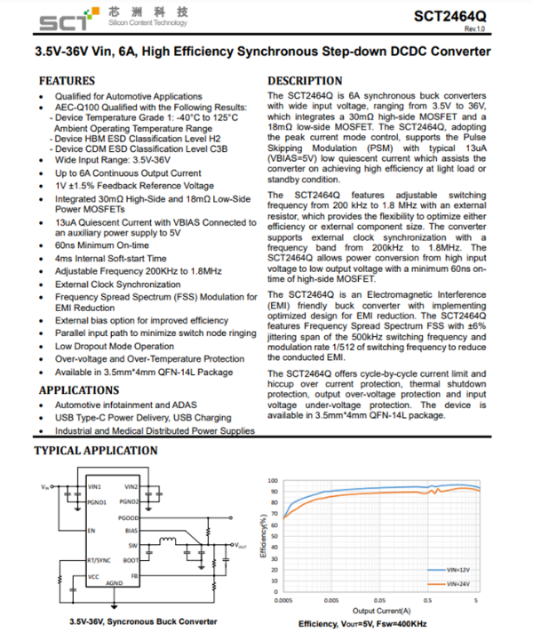
Figure 2: SCT2464Q Datasheet Homepage Example
Taking the SCT2464Q as an example, the first page mainly contains:
Main Parameters (FEATURES): such as voltage and current specifications, adjustable switching frequency, FSS (frequency jitter) function, low-dropout operation mode, external 5V for low IQ and high efficiency, AEC-Q100 temperature grade, etc.
Main Application Scenarios (APPLICATIONS): such as automotive infotainment, ADAS, etc.
Chip Features and Advantages Overview (DESCRIPTION).
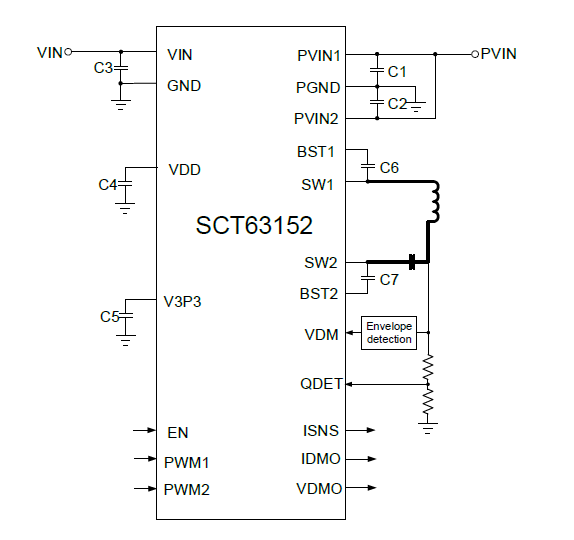
Typical Application Circuit and Efficiency Curve (TYPICAL APPLICATION).
After reading the first page, the outline of the chip has been established in your mind.
02 Chip Information and Pins
Many engineers may have questions about the complete model of the chip. This information is typically found on the second page of the datasheet. The chip's basic information (DEVICE ORDER INFORMATION) will be displayed in the following list, including: the full name of the chip, markings, and packaging information.
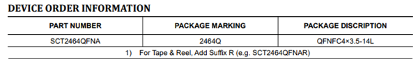
Figure 3: SCT2464Q Chip Model Example
The package is a crucial consideration for engineers during the design and selection process because the thermal management and packaging of power chips are directly related. Additionally, it's essential to consider whether the production line equipment can support fine packaging. Therefore, it's recommended to base the choice on your actual needs.
Let me know if you'd like more translation or information!
SCT2464Q Chip Model Example
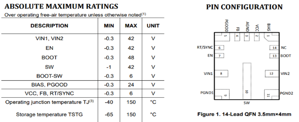
For the chip's PIN CONFIGURATION, the datasheet will provide a detailed diagram of the chip's pin layout, the maximum voltage ratings for each pin, and the pin functions. If you're unfamiliar with any abbreviations, you can find explanations in the pin function description.
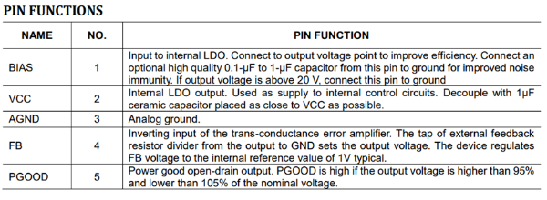
Figure 5 SCT2464Q Pin Description Diagram
Static electricity is ubiquitous in our daily lives, and we carry high static voltages around us. For sensitive instruments, this voltage can pose a deadly threat. SCT mainly rates two types of ESD (Electrostatic Discharge) models: HBM (Human Body Model) and CDM (Charged Device Model). The HBM withstand voltage of SCT2464Q is ±2KV, and the CDM withstand voltage is ±1KV, both of which are higher than the industry average.
You might be wondering about the parameter table here: Didn’t the datasheet already provide the maximum pin voltage ratings or operating junction temperatures earlier? Why are the parameters in this section a bit lower?
The recommended operating conditions are different. For example, the maximum pin voltage rating indicates that exceeding this voltage could cause permanent damage to the chip. Using the chip outside the recommended operating conditions makes it difficult to guarantee the chip's reliability. Designing within the recommended operating conditions ensures optimal chip performance and long-term reliability.
Static electricity is ubiquitous in our daily lives, and we are surrounded by high static voltages. For sensitive instruments, this voltage can pose a deadly risk. SCT primarily rates two types of ESD (Electrostatic Discharge) models: HBM (Human Body Model) and CDM (Charged Device Model). The HBM withstand voltage of SCT2464Q is ±2KV, and the CDM withstand voltage is ±1KV, both of which are higher than the industry average.
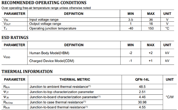
Figure 6: SCT2464Q Recommended Operating Conditions, ESD, and Thermal Resistance Diagram
THERMAL INFORMATION
The heat of semiconductor devices is primarily dissipated through three paths: from the top of the package to the air, from the bottom of the package to the PCB, and from the package pins to the PCB. The most commonly used and important parameter in electronic device heat dissipation is thermal resistance (Thermal Resistance).
Thermal resistance is an important indicator that describes the thermal conduction characteristics of a material. In addition to providing the usual thermal resistance parameters for thermal simulation design, SCT also offers a new thermal characteristic parameter, Ψjt, which helps engineers estimate junction temperature more precisely. For detailed calculation processes and thermal explanations, you can contact SCT’s technical support.
EC Table
The typical values of electrical characteristics parameters are usually data tested by ATE (Automated Test Equipment) under an ambient temperature of 25°C. The data includes typical values, minimum and maximum values, protection function thresholds, and more.
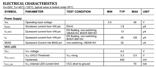
Figure 7: Schematic of Electrical Characteristics Parameters for SCT2464Q.
The key parameters differ for different products. The key parameters for DCDC include voltage and current specifications, static current, internal power MOS resistance, reference voltage, overcurrent protection threshold, soft start time, switching frequency, protection aspects (including overvoltage threshold, overtemperature threshold, BOOT undervoltage threshold), etc.
○ LDO products are relatively simpler, and the key parameters for selection include static current, input-output voltage difference, soft start time, power supply ripple rejection ratio (PSRR), etc.
○ The parameters for driver products mainly include supply voltage, static current, input-output logic, drive current, propagation delay time, etc.
05 TYPICAL CHARACTERISTICS
○ The typical performance curves for DCDC include efficiency test curves under different voltage and current conditions, line regulation curve, load regulation curve, electrical characteristic parameters changing with temperature, etc.
○ For LDO, it includes curves of static current and shutdown current changing with temperature, dropout voltage changing with output current, output voltage changing with ambient temperature or input voltage, and PSRR curves under different application conditions and frequencies.
○ For driver products, it will include curves of input threshold changing with supply voltage or temperature, delay matching changing with temperature, and propagation delay changing with ripple variation.
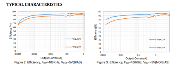
Figure 8: Schematic of Efficiency Curve for SCT2464Q
For engineers, SCT typically conducts complete efficiency curve tests under common application conditions, making it easier for everyone to refer to when designing and testing.
04 Functional Block Diagram
The internal functional block diagram of the chip provides an overview of the chip's complex internal circuitry, primarily divided into power circuits and control circuits.
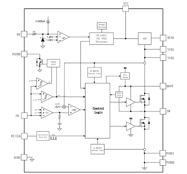
Figure 9: Schematic of Functional Block Diagram for SCT2464Q
The power circuit reflects the internal power devices of the chip, including the internally integrated power MOS, LDO, and others. The control circuit is more focused on the control modes, the working logic control relationships of each pin, and the positions and protection logic of various protection circuits.
05 Chip Function Details
The explanation of the chip functions is the most detailed content in the entire datasheet, and readers can expand on it as needed.
○ DCDC mainly includes: Overview (the overview is generally consistent with the introduction on the cover page), chip control modes (explanation of control logic and light load operation mode), usage instructions for each pin (such as EN, FB, SS, RT/CLK, BOOT, etc.), soft-start design explanation, frequency dithering function principle explanation, BOOT undervoltage and low dropout operation mode explanation, and a detailed explanation of various protection logic principles (such as overvoltage protection, overcurrent protection, and overtemperature protection).

Figure 10: Schematic of Detailed Function Explanation for SCT2464Q
○ LDO mainly includes: Overview, usage instructions for each pin (such as EN, PG, FB, etc.), soft-start design explanation, and various protection principle explanations.
○ The driver is relatively simple and mainly includes: Overview (including input-output logic table), VDD supply explanation, undervoltage protection explanation, input pin explanations, etc.
06 Typical Application Design
After thoroughly understanding the chip's performance, the sixth section provides engineers with application suggestions. This includes peripheral component design, operating waveforms, thermal performance, and recommended PCB design.
01 Peripheral Component Design
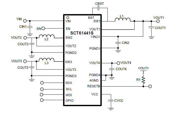
Chip manufacturers typically design a typical application circuit based on the most common application conditions.
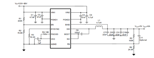
Figure 11: Schematic of Typical Application Circuit for SCT2464Q
However, everyone certainly has their own different design requirements and needs to design peripheral parameters based on actual application conditions. Below are the calculation formulas for different components, such as output voltage, switching frequency, power inductance, input-output capacitance, and so on. To further improve the convenience for engineers, SCT provides recommended component parameters for common application conditions.
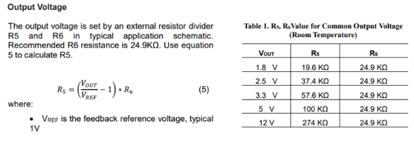
Figure 12: Schematic of Component Parameter Calculation for SCT2464Q
02 Application Waveforms and Temperature Rise
Application Waveforms
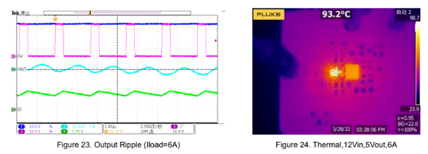
Figure 13: Schematic of Waveform and Temperature Rise Testing for SCT2464Q
At the same time, SCT has also prepared temperature rise tests under common application scenarios to help everyone determine whether the temperature rise meets the requirements.
03 PCB Recommended Design
After completing the schematic design, engineers need to begin the layout. Layout is crucial for power supply products. Poor PCB design can affect the normal operation of the chip, and many EMC issues that engineers struggle with are closely related to PCB design.
The datasheet from Xinzhu Technology provides reference suggestions on various aspects, including layout, circuit, routing of sensitive signals, and thermal dissipation, helping engineers design the optimal PCB solution.
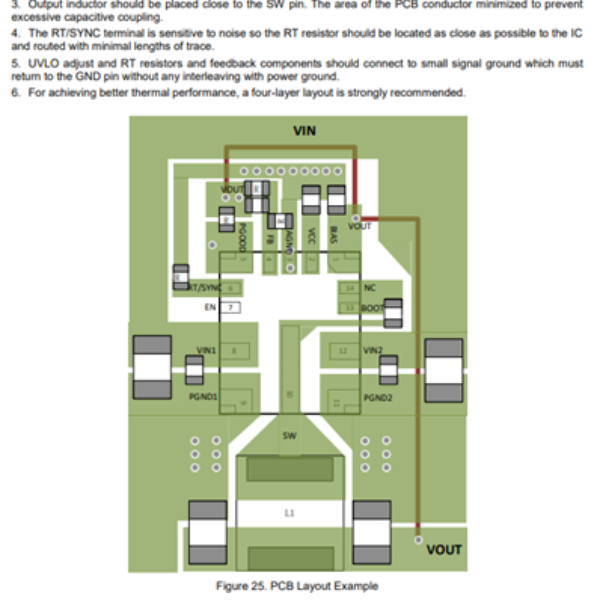
Figure 14: Schematic of PCB Recommended Design for SCT2464Q
For detailed PCB information, you can refer to the article "Xinzhu Technology: Summary of Power PCB Layout Considerations".
07 Packaging and Package Information
At the end of the datasheet, there is packaging information for this chip, helping engineers design the PCB package.
It also provides packaging information to help customers with identification, storage, and production.
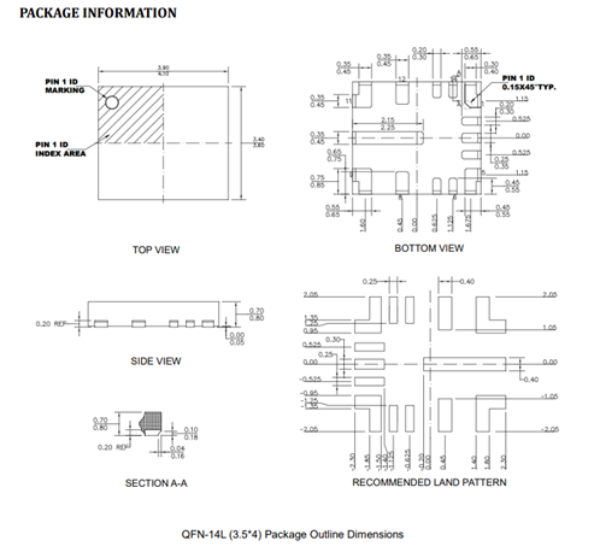
Figure 14: Schematic of Packaging for SCT2464Q
Finally, congratulations on completing the quick start guide for the chip datasheet! I believe you will be able to handle complex scenarios with ease in the future.
You can download the datasheet by logging into Xinzhu's official website at https://www.silicontent.com/. Search for the chip product you want to learn about and download the relevant materials in the Product Center.

SCT provides a wealth of design suggestions and reference data in the datasheet. We hope this can help engineers quickly master various chip applications. If you have any suggestions for the SCT datasheet, feel free to contact us.
We look forward to co-creating with all the great engineers!