Products


 0
0


In power systems, reverse polarity protection is often required to prevent wiring errors in the field, avoiding damage to circuit board components. Most electronic components do not support reverse polarity connections, while Schottky diodes offer a simple and cost-effective solution for reverse protection.
It utilizes the unidirectional conductivity of diodes, without the need for additional circuits, directly passing the power positive terminal to prevent reverse conduction. It also allows multiple power supplies to increase power capacity. However, due to the conductive characteristics of diodes, using them for reverse protection circuits inevitably leads to significant conduction voltage drops and noticeable power loss under large currents, requiring additional thermal management systems for heat dissipation.
Comparison of Three Reverse Protection Circuit Designs
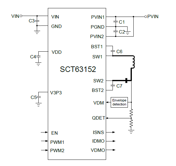
In front-end power system design, modules or subsystems directly powered by batteries need protection to prevent battery reverse connection, or to avoid dynamic reverse polarity conditions when disconnecting inductive loads from the battery. Especially in automotive battery-powered scenarios, the environment becomes more complex due to the intricate vehicle body systems, and with the higher frequency of maintenance and battery replacement, reverse polarity can lead to damage to connected subsystems, circuits, and components, resulting in significant losses.
During vehicle operation, by combining electrical transient specifications such as ISO 7637-2 or ISO 16750-2, one can more clearly observe the automotive power supply interference conditions, as shown in the diagram.
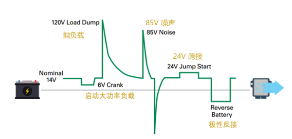
Figure 1: Automotive Battery System Power Supply Interference
Option 1: Using Diodes for Reverse Protection
Taking the 12V battery system of a passenger car as an example, when the 12V input is rapidly reversed to -12V, the output voltage remains unchanged and does not immediately drop off because the Schottky diode is reverse-biased and isolates the output from the negative voltage. At this point, the large-capacity capacitor at the output will prevent the output from dropping immediately and can supply power to the load for a short period of time before the input power is restored.
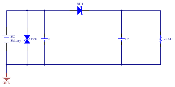
Figure 2: Schottky Diode Single-Phase Conduction Reverse Protection Circuit
This solution has the following drawbacks due to the characteristics of the diode:
Option 2: Using PMOS for Reverse Protection
To reduce the forward voltage drop of the diode, the Schottky diode can be replaced with a PMOS solution. A typical circuit is shown below:
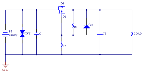
Figure 3: PMOS Reverse Protection Circuit
Replacing the Diode with a P-Channel MOSFET Q1: The body diode D1 of the P-Channel MOSFET Q1 is aligned in the same conduction direction as the positive terminal. During normal operation of the battery, the body diode D1 of MOSFET Q1 will be forward biased and conduct for a short period of time. After that, the gate voltage will be pulled below the source voltage to the Vgs(th) threshold voltage, which will turn on MOSFET Q1. When the battery polarity reverses, the gate-source voltage becomes positive, turning off MOSFET Q1 and protecting the downstream circuits from the negative voltage.
However, the PMOS reverse protection circuit resolves most of the Schottky diode's reverse protection shortcomings, but still has the following disadvantages:
Option 3: Using NMOS for Reverse Protection
For low-side series NMOS gate driving circuits, the design is simpler, and NMOS is less expensive. A typical circuit is shown below:
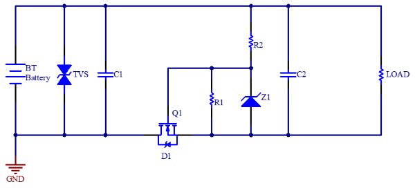
Figure 4: NMOS Low-Side Reverse Protection Circuit
However, not all systems can withstand system ground voltage jumps during switch-on or switch-off or load current transients, and this reverse protection structure splits the power ground and load ground, which significantly impacts signal integrity and alters the circuit’s EMC and EMI characteristics. Therefore, it is rarely used in automotive electronic product designs.
However, if NMOS is used for reverse protection at the power positive terminal, it can prevent reverse polarity of the input power and block reverse current flowing back to the input from the output load. This ideal diode controller + NMOS solution is clearly a better solution.
What is an Ideal Diode Controller?
An ideal diode controller has key features such as low operating static current, ultra-low turn-off current, regulated forward voltage, and fast reverse current response, which allows it to simulate an ideal diode in various applications. When connected, the power MOSFET ensures that its body diode blocks reverse current when the MOSFET is turned off. During forward conduction, the MOSFET reduces the forward voltage drop and power dissipation significantly. The ideal diode controller detects reverse current through the MOSFET and turns it off, allowing the body diode to block reverse current.
Product Analysis
The SCT53600Q from SCT Technology is a 65V-rated ideal diode controller with an internal charge pump that can fully drive the MOSFET gate above the anode during normal operation. When reverse current is detected, the forward comparator is activated, and the reverse current comparator is turned off to ensure that the MOSFET body diode completely blocks reverse DC current. A typical application circuit is shown below:
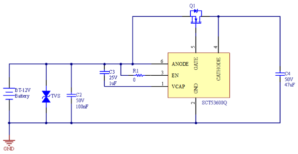
Figure 5: 12V Battery System Positive Reverse Protection Circuit
01 Forward Conduction Loss: Compared to a Schottky diode, with the same 10A load current, the diode power loss is around 5W, while an NMOS with an Rds(on) of 5mΩ has a conduction loss of only 0.5W, which saves about 10 times the energy.
02 Fast Load Response: When the forward voltage drop exceeds 50mV, the controller has a peak source current of 7mA and can quickly charge the gate during load transients, minimizing power supply voltage drop. The following is the load transient response of SCT53600Q when the load switches from a light load of 0.1mA to 3A:
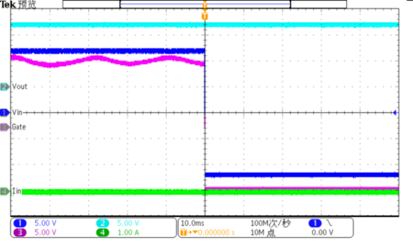
03 Input Micro-Short Circuit: When a micro-short circuit occurs at the input, the SCT53600Q will react quickly within 1µs to turn off the MOSFET, preventing reverse current from backfeeding into the short-circuited power supply. During input short-circuit, the output remains on, and the input capacitor supplies power to the load until the micro-short circuit recovers.
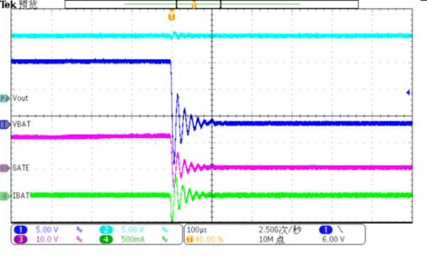
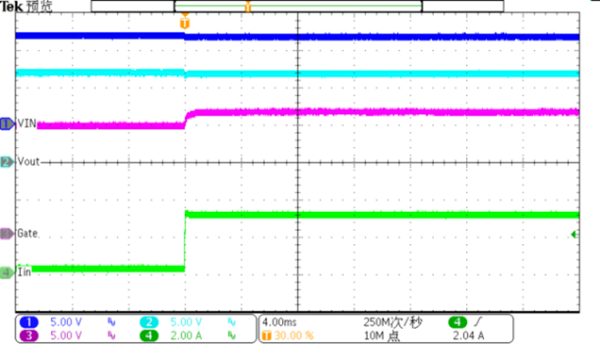
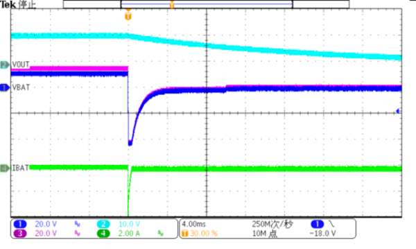
04 Static Reverse Polarity: When the input power is connected in reverse, the SCT53600Q will turn off to prevent damage to downstream circuits and components, and the output voltage is still protected. The turn-off waveform is shown below:
05 Dynamic Reverse Polarity: Based on the ISO 7637-2 Pulse1 test waveform, simulating the situation where the supply voltage suddenly drops and a reverse voltage is applied to the product’s power supply during inductive load disconnection, the ideal diode controller effectively prevents reverse polarity, as shown in the waveform below:
For systems requiring protection against input reverse polarity, the ideal diode controller + NMOS design solution provides better energy-saving performance, reverse current blocking, and voltage input margin, especially in automotive systems that pass the ISO 7637-2 test.
SCT53600Q Features: